Turning a PC on and off using an ESP8266
Table of Contents
In this post I’ll show how you can control the power state of your computer remotely using an ESP8266.
It might look useless at the first glance. Why should you even bother increasing the standby power consumption of your computer, building in a potential security hole only to emulate the push of the power button? I have a few reasons.
But first a disclaimer: Anyone screwing around with hardware while following random blog posts does so at own risk. I’m not responsible for you frying your mainboard because some thing touched another while the power was on. Additionally you should always measure what comes out of a pin and what your ESP can handle.
Reasons
When starting to think about this project a while ago my main motivation was the poorly designed case I bought. It featured a fan control and fans that make a loud grinding noise when they don’t get the full amount of power. Perfect combination.
To this day, my routine when turning on my PC is pressing power and then spamming “Fan +” at least five times to get the power to maximum and the fans happy (and silent). This is, as you might have guessed, very annoying.
Another reason to build this is being able to control the power state of my machine when streaming to the TV or otherwise being in a remote location. For even more remote locations, this code can also be adapted to use MQTT or poll the tasks from a server instead of listening.
Inspirations/Research
I originally thought of using an ESP32 and BLE but I had only a few ESP8266 around and I didn’t want to wait.
A very good example is a similar project by SilverFire which polls a PHP backend and also has support for detecting the machines current power state using the power led.
Communication
I originally used MQTT in the first version of this project but I later decided to go another way and let the ESP create a WiFi network and listen for HTTP requests.
This removes the benefit of being able to control the PC from far away but adds the benefit of just using curl or a browser to control the PC while developing and transportability. Now when there’s power, I can switch on my PC (as it should be).
Clients
Opening a shell every time I want to turn the PC on or off is too much when using the switch on a regular basis. Opening a browser takes even longer. This is not really an improvement to my previous situation.
I know! Another ESP! I will use my ODROID-GO for this, but this could (and probably will) also be made by putting a small ESP into an industrial switch, code pad or something like that.
Power
It’s also important to think about powering the switch. It needs power as soon as the switch on the power supply is turned on. And (at least in my case) some mainboards don’t have a standby power rail available. There is one 5VSB rail on the 24 pin mainboard connector. But that’s blocked and cutting/splitting the cable was too much for me at the moment. Luckily there’s the TPM header.
This pin header, which is available on some mainboards, is actually meant for extension cards/modules that can store sensitive information. This header usually has a 3V standby power pin. (In my case it’s the third from the left in the top row. Measure it before being sorry.)
Building
I started building and testing the schematic on a breadboard and only started soldering after everything worked. I advise you to do the same.
This is a (very bad) schematic of the connections to make. PWR_SW, RST_SW and PWR_LED are located in the front panel, TPM 3VSB is the standby power port, GND can be any black PSU cable (I used the one I also connect the front panel to).

It basically boils down to connecting each positive (non-ground) side of a switch to one ESP GPIO pin. Additionally that connection must be connected to a 20kΩ resistor that is connected to GND.
For the power LED, it’s basically the same but it must be connected to GPIO 16. At least on the D1 mini this is the only pin that supports the INPUT_PULLDOWN mode.
As I wrote earlier, I also wanted to connect the fan control switches, but those run on 12V, so I will leave it right now until I know how to deal with that properly. If you plan to connect pins other than the power and reset switch and the power led to the ESP, measure their voltage before doing so.
The ESP gets its power from TPM 3VSB or any other standby power rail and its GND is connected to the same GND as the resistors.
Here’s a picture of the first (partially wrong) PCB. The error here is that the power LED is connected to GPIO14 which will result in digitalRead always returning HIGH.
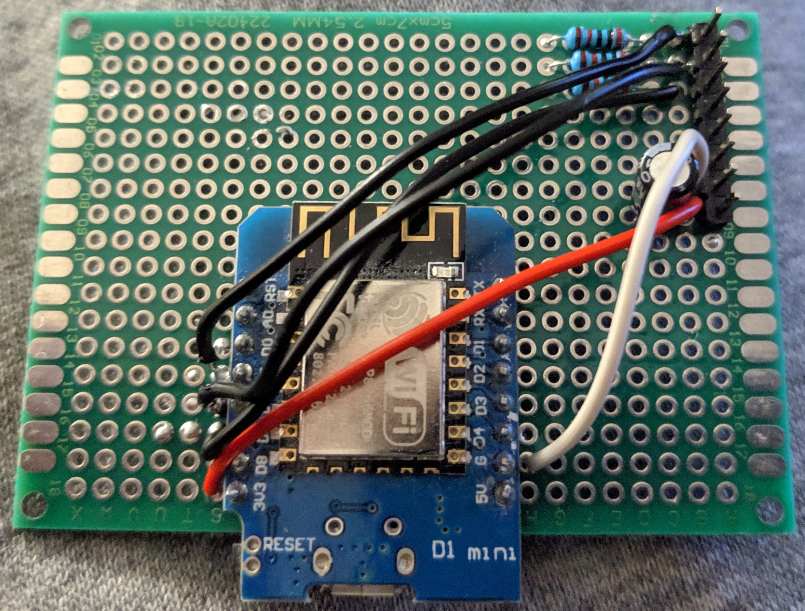
Pins and plugs seemed to be the most obvious choice for my case. When flashing the ESP (which I do a lot during development), it’s not a good idea to leave everything connected to it.
My choice of using plug-in cables for connecting to the PC came with some benefits. First of all, connecting my front panel was very easy.
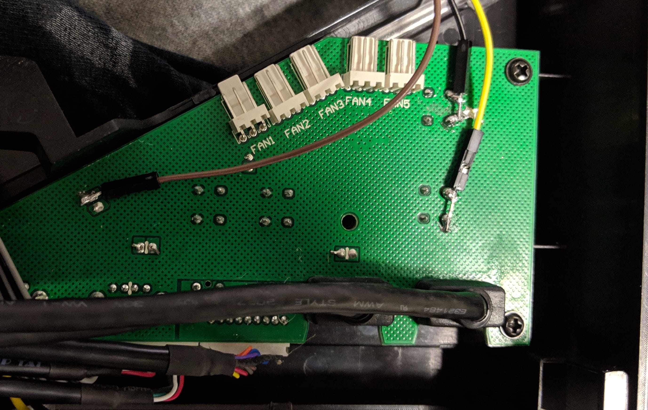
In the following picture, the leftmost solder joint is the plug-in cable connected to the positive side of the power LED. The ones on the right are the positive sides of the power and reset switches.
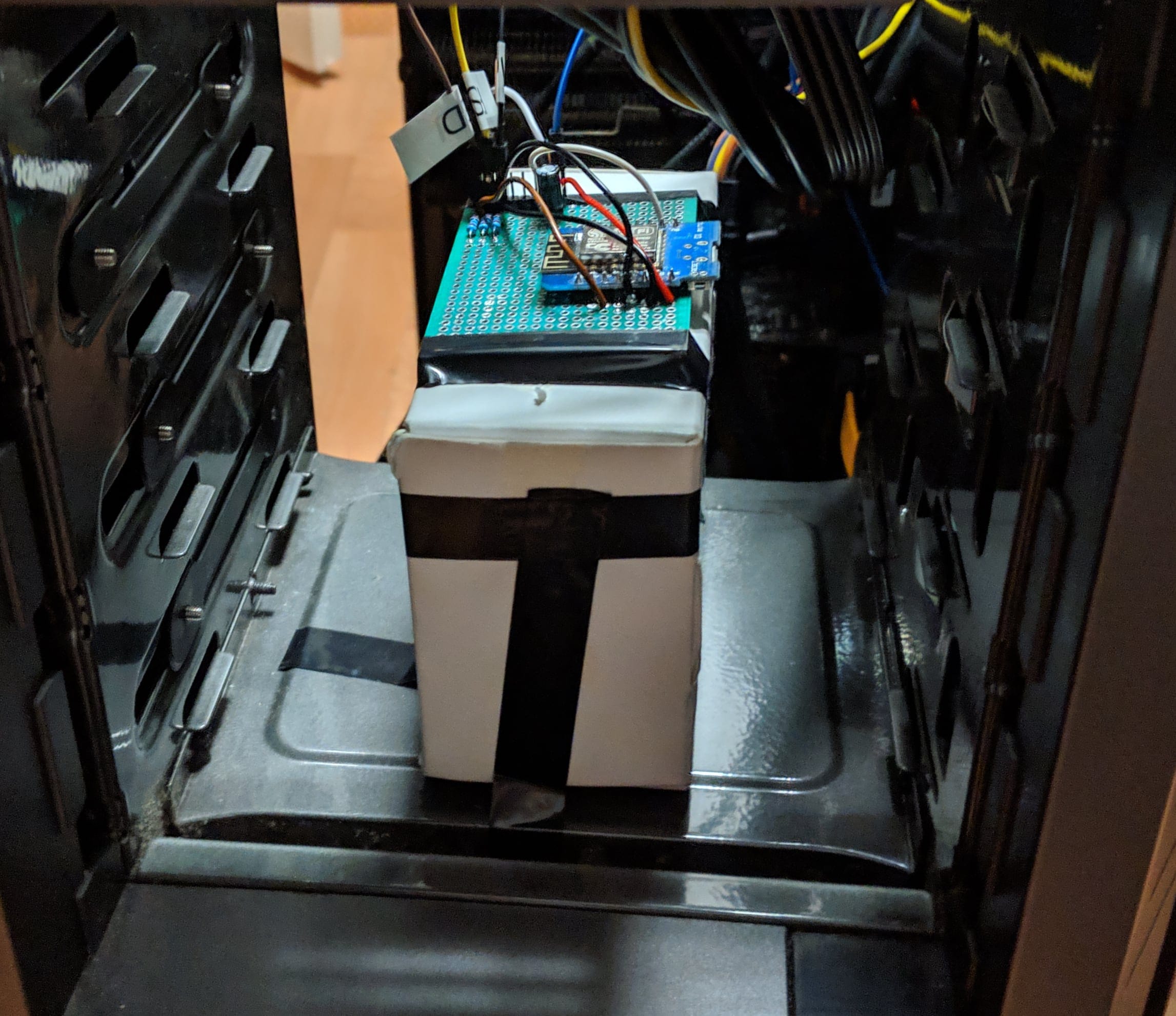
Now I have three wires dangling down into the area where normal people would have their DVD drive (I don’t have one). Because those wires are a bit too short or the drive bay is too high (or too empty) I had to install a small cardboard box that acts as a placeholder to prevent the ESP from pulling on its solder joints:
Coding
I’m using PlatformIO for development. In most cases, using PlatformIO with a particular board only involves installing a serial driver and finding out the device path to use.
Concerning the cheap D1 mini models featuring a CH3**G serial chip and macOS, you can probably use this driver (VirusTotal report) I originally found here.
When creating a new project with PlatformIO, all the needed libraries to compile code for the device you are using are downloaded automatically if available. The IDE creates a project directory with a main.cpp file containing the standard Arduino methods setup and loop. We need the file, but not it’s content. Delete it.
Includes / Fields
This project only needs three includes. All of those are already available when you select that you want to create a new project for an ESP8266:
#include <Arduino.h>
#include <ESP8266WiFi.h>
#include <ESP8266WebServer.h>
After the includes were added, it could happen that PlatformIO complains about missing dependencies. In that case, press the build button once to let it compile.
Now let’s add some defines and variables/fields we need later. Those two define how long button presses take in milliseconds:
#define PWR_OFF_TIME 5000
#define PUSH_TIME 400
The next three define the GPIO numbers of the pins we’re using. You can query any image search engine for <board_name> pinout. If you use a D1 mini, you can also use this link.
#define PWR_PIN 13
#define RST_PIN 12
#define STATUS_PIN 16
Now we declare some variables. The first two are the bssid and passphrase for the WiFi the ESP will create. The third one declares a web server running on the ESP AP’s IP on port 80.
const char* ssid = "PCSwitch";
const char* password = "npf4kewCLbHez5MP";

ESP8266WebServer server(WiFi.softAPIP(), 80);
The following is also needed if you want to read the current voltage of the ESP. This is a bit inaccurate and you might not be interested in it. If you’re not, please also leave out the call to ESP.getVcc() later on.
ADC_MODE(ADC_VCC);
Methods
In this paragraph I’ll list and describe all the methods used on the program.
The first one is a simple fail loop. When an error occurs that prevent the switch from working at all (ex. WiFi fails to start), it just starts blinking forever.
void failLoop() {
    while(true) {
        digitalWrite(LED_BUILTIN, LOW);
        delay(100);
        digitalWrite(LED_BUILTIN, HIGH);
        delay(100);
    }
}
This method activates a given pin for a given time of milliseconds. This is basically what pushes the buttons.
void togglePin(int pin, int ms) {
    digitalWrite(pin, LOW);
    pinMode(pin, OUTPUT);
    delay(ms);
    pinMode(pin, INPUT);
}
The next method reads the state of the power LED. As I wrote before it’s important that the pin supports the INPUT_PULLDOWN pin mode.
bool isPoweredOn() {
    return digitalRead(STATUS_PIN) == HIGH;
}
Since the ESP should also return as much information as it has available when it’s responding to a request, I set a String containing this information as response body. This method checks the state of the power LED, reads the ESP’s current IP and voltage and returns it as a comma (and space) separated string.
String getStatusString() {
    return String(isPoweredOn() ? "ON" : "OFF") + ", " +
        WiFi.softAPIP().toString() + ", " +
        ESP.getVcc()/1024.00f + "V";
}
This method does the forced power off. It holds the power button for the time of milliseconds defined as PWR_OFF_TIME. While it’s executing, the built-in LED will be on.
void do_powerOffForce() {
    digitalWrite(LED_BUILTIN, LOW);
    togglePin(PWR_PIN, PWR_OFF_TIME);
    digitalWrite(LED_BUILTIN, HIGH);
}
The next method executes a power on. I wanted to go down the safer road implementing a separate on and off method that (opposed to the forced one) checks the current power LED state and refuses to execute (returning a 409 response) when the desired result equals the current state. While it’s executing, the built-in LED will be on.
void do_powerOn() {
    if(!isPoweredOn()) {
        digitalWrite(LED_BUILTIN, LOW);
        togglePin(PWR_PIN, PUSH_TIME);
        digitalWrite(LED_BUILTIN, HIGH);
    } else {
        server.send(409, "text/plain", "ERR, " + getStatusString());
    }
}
The next method executes a power off. Same as the one above but the other way around. While it’s executing, the built-in LED will be on.
void do_powerOff() {
    if(isPoweredOn()) {
        digitalWrite(LED_BUILTIN, LOW);
        togglePin(PWR_PIN, PUSH_TIME);
        digitalWrite(LED_BUILTIN, HIGH);
    } else {
        server.send(409, "text/plain", "ERR, " + getStatusString());
    }
}
This method executes a reset. While I as well could ignore the power LED on this one, I noticed that my computer would only react to the reset when the power is on (ie. it will not turn on by pressing reset) so I built in the same check. While it’s executing, the built-in LED will be on.
void do_reset() {
    if(isPoweredOn()) {
        digitalWrite(LED_BUILTIN, LOW);
        togglePin(RST_PIN, PUSH_TIME);
        digitalWrite(LED_BUILTIN, HIGH);
    } else {
        server.send(409, "text/plain", "ERR, " + getStatusString());
    }
}
Next up is a method that configures the endpoints of the ESP8266WebServer we declared earlier. To avoid writing even more methods, the callbacks are lambdas (embedded/inlined methods).
void configureEndpoints() {
    server.on("/pcswitch/pwr_off_force/", [] () {
        do_powerOffForce();
        server.send(200, "text/plain", "PWR_OFF_FORCE, " + getStatusString());
    });

    server.on("/pcswitch/pwr_off/", [] () {
        do_powerOff();
        server.send(200, "text/plain", "PWR_OFF, " + getStatusString());
    });

    server.on("/pcswitch/pwr_on/", [] () {
        do_powerOn();
        server.send(200, "text/plain", "PWR_ON, " + getStatusString());
    });

    server.on("/pcswitch/reset/", [] () {
        do_reset();
        server.send(200, "text/plain", "RESET, " + getStatusString());
    });

    server.on("/pcswitch/status/", [] () {
        server.send(200, "text/plain", "STATUS, " + getStatusString());
    });

    server.onNotFound([] () {
        server.send(404, "text/plain", "Not Found");
    });
}
Next up is the setup method. It does initial stuff like setting up the WiFi access point, setting the pin mode and configuring the web server.
This method is automatically run by the ESP firmware after the device boots or a reset occurs.
void setup() {
    pinMode(LED_BUILTIN, OUTPUT);
    WiFi.mode(WIFI_AP);

    pinMode(STATUS_PIN, INPUT_PULLDOWN_16);

    if(WiFi.softAP(ssid, password, 3, true, 8)){
        digitalWrite(LED_BUILTIN, LOW);
        delay(50);
        digitalWrite(LED_BUILTIN, HIGH);
    } else {
        failLoop();
    }

    configureEndpoints();
    server.begin();
}
And finally there’s the loop method. This is also run automatically by the ESP firmware but (as the name suggests) all the time all over again until the device is turned off. Since this ESP only runs a web server, it’s fairly small.
void loop() {
    server.handleClient();
}
You can find the whole file with some comments as a snippet on GitLab.
Testing
Right now, the code you wrote should compile. If you have any leftover errors, check the compiler output. I noticed that it seems necessary for methods that are used to be declared beforehand, so you might adjust the order of your methods (it compiles from top to bottom as it seems).
After the ESP is flashed, it should briefly blink on boot. After that the next time it will blink is when it pushes a button.
To test if it’s working, you can simply connect something like your phone to the WiFi the ESP created and open a browser to http://192.168.4.1:80/pcswitch/status (which is the default IP). If the connection is refused, make sure you are in the correct WiFi and use the Gateway IP Address if it’s different.
Final assembly
Now it’s time to put the ESP into the computer. I’d advise to make sure that the ESP is easily accessible in case another flash is needed later to fix bugs or add features (like a temperature sensor maybe?).
Also it might be wise to test the connections/setup before using glue, screws or soldering stuff.
Here’s a video of the initial version of this project which just connected to my WiFi, sent a message using MQTT and pressed the power button regardless of commands.
After support for listening to MQTT was implemented, I was able to actually control my pc using a laptop I had nearby.
And after the really, really awesome suggestion by @nsueper that I could as well use my ODROID-GO as a remote for the ESP, I did a rewrite and created the version shown here. There is also a video of the ODROID-GO in action:
I plan to wrap up all the things I came across when developing the ODROID-GO part of this in another blog post. Unfortunately, I can’t yet say when it will be ready.
I really hope this project inspired you to create something similarly useless but fun.
Have a nice day.
Update (July 2020): After I shot the above videos and photos I simply put my computer back together. I now have the ESP running as is since over a year and besides some random wakeup from standby once every few months (which might also be automatic Windows updates, idkfs) it works flawlessly.
Update (December 2021): I had to take out the ESP assembly to make way for a DVD drive, after removing the ESP the random wakeups kept appearing, so this mod probably wasn’t the cause. I was able to fix the random reboots/wakeups by reinstalling the OS.
If you have any questions, feel free to contact me and also feel free to share your crazy projects with me (and the world).